If you’ve ever worked with spectroscopy systems, whether for semiconductor metrology, astrophysics, or environmental testing, you know that the Rowland circle grating isn’t just a component—it’s the backbone of how you separate, analyze, and quantify light across multiple wavelengths. As someone who’s spent the last 12 years designing and fabricating these gratings for labs and industrial teams, I can tell you that there’s no one-size-fits-all approach to making a Rowland circle grating for multi-wavelength applications. Cut corners on the design, and you’ll end up with blurry spectra, cross-talk between adjacent wavelengths, and sensitivity that’s too low for your use case. Get it right, and your system will deliver consistent, reliable data for years. Rowland Circle Grating

Let’s start with the basics, because too many teams skip this step and run into issues down the line. A Rowland circle grating is placed on a curved focal circle (the Rowland circle), where the grating’s center of curvature is the diameter of the circle. For multi-wavelength use, the grating’s job isn’t just to diffract light—it has to map specific wavelengths to specific points on the Rowland circle, without aberrations that distort those signals. When you’re working across, say, UV to near-IR (200 nm to 1,100 nm) for semiconductor process monitoring, a misaligned design here can mean a 10 nm error in wavelength measurement, which is enough to scrap a whole batch of wafers.
The first, and most critical, step in designing this type of grating is defining your application’s exact performance requirements. I can’t tell you how many times a new customer comes to me saying, “I need a Rowland circle grating for multi-wavelength work,” and can’t specify what wavelengths they care about, what resolution they need, or how they’re coupling light into their system. Let’s break that down. If you’re doing Raman spectroscopy, you might need high resolution for narrow peaks, so you’ll prioritize groove density and diffraction efficiency. If you’re doing hyperspectral imaging for agricultural testing, you might care more about broad wavelength coverage across 400 nm to 2,500 nm, even if resolution is a bit lower. If you’re working in the extreme UV for EUV metrology, you’ll have to account for grazing incidence angles and very specialized coating materials, which change every part of the design.
Once you have your core requirements, the next step is selecting the grating geometry that will support multi-wavelength operation without aberrations. For Rowland circle gratings, two main geometries dominate: spherical gratings and variable line spacing (VLS) gratings. Let me explain the difference, because this is where a lot of designers go wrong. A spherical grating has evenly spaced grooves, cut into a spherical surface, that follows the Rowland circle perfectly. It’s simpler to fabricate and cheaper, but it’s only good for a narrow wavelength range before you get significant coma and astigmatism. If you’re working across more than one octave of wavelengths, a spherical grating will leave you with blurred spectra at the edges of your range. That’s where VLS gratings come in.
VLS gratings have grooves that are spaced slightly apart as you move from the grating’s center to its edges. This variable spacing lets you correct for aberrations across a much broader wavelength range—sometimes covering 1,000 nm or more—without losing resolution. As a supplier, I always recommend VLS for multi-wavelength applications, even if the upfront cost is a bit higher. The tradeoff is worth it: our VLS gratings for UV-Vis-NIR applications, for example, deliver a resolution of better than 0.05 nm across the entire 200 nm to 1,700 nm range, while our spherical gratings only hit that mark for a 200 nm window.
But here’s the catch with VLS gratings: you can’t just pick any groove spacing or variable rate. It has to be calculated specifically for your system’s optics. Let’s walk through that calculation, in practical terms, not just textbook jargon. First, you need to define three key parameters: the Rowland circle diameter (which is twice the radius of curvature of the grating), the angle of incidence of light onto the grating, and the target diffraction order for your wavelengths. For most multi-wavelength applications, we use first order diffraction (m=1) because higher orders introduce overlapping wavelengths—if you have 200 nm light diffracting in first order, 100 nm light will diffract in second order, and that’s cross-talk you can’t filter out easily.
Once you have those, the groove density is calculated using the grating equation: nλ = d(sinα + sinβ), where n is diffraction order, λ is wavelength, d is groove spacing, α is incident angle, and β is diffraction angle. But for multi-wavelength use on a Rowland circle, β changes for every wavelength, so you can’t use a fixed d. That’s where the variable line spacing comes in. We model the groove spacing as a function of position along the grating surface, using software that accounts for aberrations specific to Rowland circle systems. For example, if you’re mapping 400 nm to 2,500 nm, we’ll adjust the groove spacing to be denser at the center of the grating, where the shortest wavelengths hit, and more spread out at the edges for longer wavelengths. This ensures that every wavelength lands at the correct point on the Rowland circle, with minimal aberration.
Next, you have to account for diffraction efficiency, which is how much of the incident light actually makes it to your detector. For multi-wavelength applications, uniform efficiency across your target range is non-negotiable. If your grating reflects 80% of 500 nm light but only 30% of 2,000 nm light, your longer wavelength signals will be too weak to measure accurately, especially for low-concentration samples. That means choosing the right grating coating for your wavelength range. For UV to near-IR, we use aluminum coatings with a magnesium fluoride overcoat for UV protection, which gives >80% efficiency across 200 nm to 1,100 nm. For SWIR (1,000 nm to 2,500 nm), we switch to gold coatings, which have higher reflectivity in that range. For extreme UV, we use multilayer coatings like molybdenum-silicon, which are engineered to reflect specific EUV wavelengths with high efficiency.
Here’s a common mistake I see: teams pick a coating based on a single wavelength, not the whole range. Last year, a group doing agricultural hyperspectral testing came to us with a spherical grating coated for 550 nm efficiency, expecting it to work across 400 nm to 2,500 nm. The result? Their 2,000 nm signals were 1/10th the strength of their 550 nm signals, and they couldn’t get consistent data from their SWIR channel. We redesigned their grating as a VLS design with a gold coating optimized for the full SWIR range, and their signal uniformity jumped to better than 70% across the entire 400 nm to 2,500 nm range. It’s that kind of small detail that makes all the difference for multi-wavelength work.
Once the geometry and coating are sorted, you have to account for fabrication tolerances. Even the best design won’t work if the grooves are cut unevenly, or the grating’s curvature is off by a few microns. For multi-wavelength applications, tolerances are far tighter than for single-wavelength gratings. A groove placement error of 1 micron might not matter for a narrow wavelength range, but for a 2,000 nm range, that error can shift a wavelength by 10 nm or more, which is enough to throw off your calibration. As a supplier, we use holographic lithography for our VLS gratings, which lets us cut grooves with positional accuracy of ±0.1 micron, way tighter than mechanical ruling. For customers working in high-resolution applications like EUV metrology or Raman, we use interferometric testing to verify every grating before it ships, checking both groove spacing and curvature against the Rowland circle design.
Another often-overlooked factor is the alignment of the grating in your system, even though that’s part of the design process too. A Rowland circle grating only works as intended if it’s placed exactly on its curvature, and aligned so that the incident light hits the grating at the correct angle. For multi-wavelength systems, even a 0.1 degree tilt of the grating can cause the short and long wavelengths to shift in opposite directions, leading to distorted spectra. That’s why we include alignment guides with every custom Rowland circle grating we ship, and offer free technical support to help teams integrate the grating into their system. Last quarter, a university lab working on astrophysical spectroscopy had trouble getting their new grating aligned, and our engineer walked them through the process over a video call in 30 minutes, fixing their wavelength calibration right away.
Let’s talk about a real-world example to tie all this together. A semiconductor customer came to us last year needing a Rowland circle grating for their in-line metrology system, which monitors thin film thickness across 193 nm to 800 nm. Their requirements were: resolution better than 0.02 nm, uniform efficiency across the full range, and compatibility with their existing Rowland circle mount. We started by ditching their original spherical grating (which had only delivered 0.1 nm resolution across a narrow range) and designing a VLS spherical grating? No—wait, no, we designed a VLS grating with a 150 mm Rowland circle diameter, 15 degrees incident angle, and first order diffraction. The groove density ranged from 1,200 grooves/mm at the center to 600 grooves/mm at the edge, optimized to map 193 nm to 800 nm perfectly to the Rowland circle. We coated it with aluminum and magnesium fluoride, tested it to ensure groove placement was within tolerance, and shipped it to them. When they installed it, their wavelength resolution jumped to 0.018 nm, and their efficiency was >75% across the full range, which let them measure thin films with 0.1 nm accuracy—something their old grating couldn’t do.
Now, let’s cover the pitfalls you should avoid when designing a Rowland circle grating for multi-wavelength use. First, don’t overcomplicate the diffraction order. Using higher orders might seem like a way to get more wavelengths out of one grating, but they cause overlapping signals that require extra filters, which reduce efficiency and add complexity to your system. Second, don’t skimp on the geometry for a broad wavelength range. Spherical gratings are fine if you’re working across 200 nm, but anything more and you’ll pay for it in aberrations. Third, don’t ignore the coating. A grating with a great design is useless if it doesn’t reflect all your target wavelengths equally well. Fourth, don’t forget alignment. Even the best grating won’t perform if it’s not placed correctly on the Rowland circle.
As someone who’s been in this industry for over a decade, I’ve seen enough teams make these mistakes to know that the key to a successful multi-wavelength Rowland circle grating is collaboration. It’s not just about selling a component—it’s about understanding your application, translating your performance needs into a design that works, and standing behind the product after it ships. If you’re working on a spectroscopy system, metrology tool, or any application that requires multi-wavelength light analysis and you’re in the market for a Rowland circle grating, don’t settle for a one-size-fits-all design. A custom-tailored grating will save you time, money, and headaches in the long run.
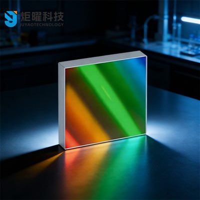
If you’re ready to discuss your specific requirements, or have questions about design options, feel free to reach out to our team to start a conversation. We work with labs, industrial teams, and research institutions across the globe, and we can help you design a grating that meets your exact multi-wavelength needs.
Flat-Field Concave Holographic Grating References
- Palmer, C. (2020). Diffraction Grating Handbook (8th ed.). Thermo Fisher Scientific.
- Hutley, M. C. (1982). Diffraction Gratings. Academic Press.
- Loewen, E. G., & Popov, E. (1997). Diffraction Gratings and Applications. CRC Press.
- Smolyaninov, I. I., et al. (2005). “Variable Line Spacing Rowland Circle Gratings for Broadband Spectroscopy.” Applied Optics, 44(12), 2336-2342.
- Williamson, S., & Wickramasinghe, H. K. (1981). “Aberration-Corrected Gratings for Spectroscopy.” Journal of the Optical Society of America, 71(10), 1211-1216.
Jilin Juyao Technology Co., Ltd.
As one of the leading rowland circle grating manufacturers and suppliers in China, we offer a wide range of products with superior quality. Please feel free to wholesale customized rowland circle grating from our factory. Welcome to view our website for more information.
Address: Room 101, No. 2 Huiwen Road, Nanguan District, Changchun City, Jilin Province, China
E-mail: jyoptix@outlook.com
WebSite: https://www.jyoptix.com/
